PSoC5LP based RF Wattmeter
This started as a port from the Arduino Nano headless code from the first phase of this project with the M5Stack. I wanted a higher performance AD Converter without the noise problems the M5stack (using the internal AD) had. I like the PSoC free IDE with full debugger and C language better also.
This page is about the work done on the PSoC5LP (CY8CKIT-059 dev module) for full remote control and monitoring from a desktop. I added some displays back on for use embedded in a RF amplifier, as a dedicated desktop display, or as a portable instrument using a 10GHz dual detector module.

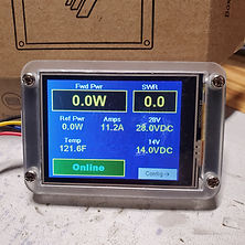

Above are pictures of the 2.4" Nextion LCD touchscreen I programmed for vertical and horizontal layouts. On the right is a 0.96" OLED display.

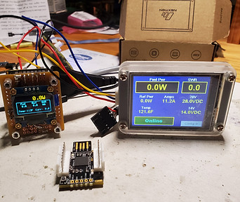
Above left is a collection of CPUs and displays used for this project so far.
Shown is a 3.5" Nextion loaded with the HF kit radio "uBITx" display file. Attached to it is the optional IO extender board. It has 6 switches, a buzzer and a LED.
The upper row left to right:
1. PSoC5LP dev board CY8CKIT-059
2. M5Stack Basic Core module
3. Kitprog programming snap-off board (PSoC5)
4. 4 channel ADS1115 AD Converter module
5. M5stack ADS1100 single channel 16bit ADC "Unit"
Above right photo is the 2.4" Nextion LCD touchscreen, the 0.96" OLED mounted with a KitProg CPU module on the back.
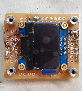


Above are the OLED and teh KitProg CPU ready for mounting behind a front panel. On the proto board are voltage dividers and a 5V regulator. It will measure 28VDC, 14VDC, and eventually current and temperature sensors.
I wanted to embed some of these into some newly built VHF and UHF high power amplifiers lacking metering so I added a 0.96" OLED display with 128x64 dot matrix connected via I2C. It is sharp looking, works well, but is a bit small. Perfect for my small 432 amp control box, nothing larger will fit that one. For my 222MHz amp, there is a large empty front panel waiting for something nice looking and larger.
I spotted the Nextion line of standalone programmable intelligent graphics displays. It used a PC based WSIWYG editor to configure the device with text fields and controls and then communicates with any size CPU with ASCII character command and event messages over a UART at typically 9600-115K baud rates. There is virtually no load on the CPU making it perfect for Arduinos and other small embedded CPUs. You can upload the display build from your PC via USB TTL converter or an SD card. The UART method will step up to 115200 baud for fast uploads. It can resize photos and generate font libraries easily which get loaded to the display .HMI file which is uploaded to the CPU also. I am using the enhanced version of the 2.4" display which features 8 GPIO ports, EEPROM, RTC, and a bit more performance. Display range from 2.4" to 10" today. This 2.4" was around $26 shipped including the optional casing. There is a GPIO extender cable and card available for a few bucks. I later moved this to a 3.5" size display.
The PSoC5 is programmed using the C language. Arduino uses the C++ based compiler. An Arduino library for the Nextion is provided on GitHub, and some searching led me to a user-ported C version. I adapted it to the PSoC5 and found a few bug or worse, maybe a compiler bug.
There is a learning curve for this but once you get through it you realize it is easy, just need to learn the library and syntax oddities. There are no example files found easily so some online videos, some forum comments, rereading the command list 20 times, and a lot of trial and error. The hardest part was getting the serial port section of the library adapted. It was actually easy looking back but when I first looked at it in the sea of warnings on my initial file imports I removed too much code to get things working. Later I added it all back only changing a few key lines. I ran into what I think is a GNU C compiler bug regarding passing string pointers between functions in separate source files. I was only getting the first character of my send commands. I worked around that by declaring the variable as a global extern in each of the source files.
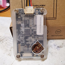
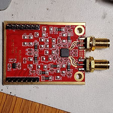
Throughout this page you can see some display layout experiments. One at the top of this article shows a background picture of my old EME tower setup. I have settled on a solid background horizontal layout. I added more pages like a 2nd Config page intended to facilitate sensor calibrations. I hooked up the OLED on the I2C bus and can run both easily with excellent ADC performance (set at 20bit resolution). The back side has a coin cell holder for the RTC. The red board is the dual channel 10GHz RF detector model ADL5519 from http://SV1AFN.COM.
I had several approximately 1" square KitProg breakoff programming boards laying around looking for something to do. I broke down and studied the Booloader documents. The KitProg User Guide actually walks you through how to program the KitProg with your own app. After a short timeout the KitProg bootloader will jump into your own app. I set up my app running on the main target board to work with the same pins available on the Kitprog. The only change needed to run on the Kitprog is to add the bootloader component to the TopDesign drawing, select a new target model (-039 device vs the dev module -097) then use the Bootloader Host utility to send it all to the KitProg Flash memory in a few seconds.
Making use of the Kitprog for cases where you do not need more than the dozen IO pins makes the PSoC CY8CKIT-059 dev module a super value with 2 high functioning CPUs at $10 to $15 for each dev module. Plus the internal ADC and Vref and AMux performance is much better than the Arduinos I have tested so far.
The code is added to my GitHub repository for the RF Wattmeter joining the M5Stack and Nano headless versions posted there.
https://github.com/K7MDL2/RF-Power-Meter-V1


Above are pictures of the 3.5" Nextion LCD touchscreen version. The cabinet is a re-used 1985 vintage 5" analog wattmeter with a slightly sloped back front panel. Can replace the printed panel cover with something fancy or reuse the hole for a power switch. Inside is a PSoC5 CPU with the KitProg board snapped off, the 10GHz dual detector (which is a double 8318 on the same silicon), USB port, USB 4 port hub with onboard USB to UART converter, 12VDC, 5V regulator. For easy development purposes, to program the display I will likely route the display UART RX and TX lines from the display through either a DPDT switch or through CPU I/O pins to a connector on the back for a USB-Serial TTL converter.
The LCD bezel is CNC cut black acrylic sourced from Computer Freaks Anonymous at http://compfranon.uk. It mounts the display board with 4 screws on the back. I used thin strips of double sided tape to stick it to the front panel temporarily. The white is protective film which of course will come off once I am done fiddling with construction.
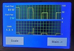
With more space I added dBm values on the main page, made the controls larger, and added a new graphing screen. The top graph has 2 traces, Forward and Reflected power, and the bottom graph is SWR. The scales can be changed between 10 and 2000W. I have a mystery SWR spike to resolve. It may be real. The SWR trace turns red over 2.0. The code to create and update the graph and change scales is all on the display module, the host only sends up the power and SWR values. A timer run on the display reads the power and scale values and executes the right scaling. Easy.