Acerca de
Teensy SDR Project

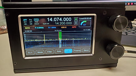
Teensy 4 Software Defined Radio Project
Winter 2020-2021 I decided to build my own Arduino SDR and after looking around I found the Keith'sSDR group at keithsdr@groups.io | Home
The project was focused on building a simple DIY SDR radio based on Arduino on the very capable Teensy 4 series CPU. I have been using the Teensy 4 for my RF Wattmeter/Band Decoder project, now realized in a RF tolerant PCB design. I jumped in. I was mostly software focused and wanted to create a high resolution spectrum display and commercial looking UI features primarily to perform as compact low power IF radio for my VHF and microwave transverters.
I extended the KeithSDR with customizable table drive UI elements then moved onto figure a way to get a high resolution spectrum and waterfall display, eventually running at multiple FFT sizes. Today that is 1024, 2048 and 4096 both I and Q. I use multiple FFT sizes to achieve pan and zoom with no extra compute required. I also wanted the touch screen to evolve to not miss physical controls much, if at all. On the 7" 1024x600 display version I have not used hardware controls for a year.
The spectrum display code was developed to be plugged into an Arduino project and is now in the form of a library. The properties are easily configurable with a utility function to create parameters for one row in a table. Updating this much data (spectrum draw, waterfall scrolling) on the touchscreen displays in use for the project was not possible. After looking at the RA8875 and RA8876 spec sheet and sample I implemented the display controller Bit Move Engine feature. This lets you offload the CPU and SPI bus by having the display controller move blocks of screen and leveraging layers, which may be drawing invisibly if desired. Now the CPU can focus on the audio and Control, perform higher FFT and higher sample rates with a relatively low cost and good looking display in multiple sizes.
The display looked good, the capacitive touch screen was good, but the included gesture engine was not working. So I wrote my own gesture engine and now have a very performative muti-touch capability. You can fully operate the many radio features with touch alone. Control hardware such as switches, encoders, and i2c RGB LED encoders are supported also.
The audio library used is OpenAudio_Library on GitHub maintained and upgraded regularly by W7PUA. One of the biggest improvements he made was converting the library from 16-bit integer to 32-bit floating point. He has added other useful features such as noise blanker and Noise reduction and most recently a means to auto detect and correct an i2s audio byte steam synchronization bug in the Teensy/SGTL audio card interface that has existed for years, aka the "Twin Peaks" FFT mirror image problem.
The RF hardware started out with a QRP-Labs receiver. Several project members worked on transmitter hardware. NT7V sent me a RX/TX SDR board that was a kit 5 or 6 years back. I then added transmit modulation recently (still software work to do though on this). I added support for SV1AFN 10 band preselector with a LNA and digital step attenuator and i2C encoders.
I acquired 2 Hermes Lite 2 (HL2) SDRs and built 2 PiHPSDR controllers, one encoded in a Hammond box with milled front and back panels using a PCB with several dual encoders and lots of switches. The other controller is smaller with a few controls. Both are touch and VFO encoder enabled with the official Pi 7" touchscreen and RPi4B CPUs. I thought about putting my Teensy SDR in front of a HL2 which would require fast ethernet data handling, would be a lot of work. The HL2 fell victim to parts shortages and can no longer be built as of April 2022. I love my PiHPSDR controllers and the HL2s and use one for transverter IF rig duty.
My Teensy SDR was still looking for full RX/TX with filtering and some TX power. I was fighting system noise issues with the collection of off-the-shelf modules wired together and decided I would rather focus on the software. I then found the RS-HFIQ 5W transceiver form HobbyPC.
Amateur Radio: RS-HFIQ 5W HF SDR Transceiver (hobbypcb.com)
I developed a Teensy USB Host to RS-HFIQ interface library. It allows the Teensy to control the RS-HFIQ over the Teensy 4 USB Host port. I have extended my software with a USB serial CAT port using the RS-HFIQ OmniRig V1 interface rig file. You can use programs like WSJTX or the Teensy SDR radio to tune, change bands and they will stay in sync.
As of April 2022 the latest hardware evolution packages the RS-HFIQ in a 53mm deep version of the RS-HFIQ Hammond 1455 series box. The 4.3" RA8875 display fits behind the front panel milled by Front Panel Express, same as I did for my big PiHPSDR controller. A member of the KeithSDR group, John, N0CTL developed a few display to SPI bus adapters and that grew to multiple revisions of a Teensy motherboard that fits on the back of the RA8875 or RA8876 displays eliminating wiring. Not only does this make construction easy and fast, it also helped eliminate the several sources of noise from SPI bus, power supply, and the display RFI. It is a 4 layer board and itself acts as a radiation shield. This is useful for the RS-HFIQ being located 3/4" away in the same small box (160mm x 103mm x 53mm, Hammond 1455N1601BK).
Teensy Motherboard V2 thread: https://groups.io/g/keithsdr/topic/pcb_v2_update_and/90596909
PCB files: https://oshwlab.com/jrsphoto/teensy-sdr-display-processor_copy_copy_copy
Teensy 4 SDR project code on GitHub: K7MDL2/KEITHSDR: Teensy4.X with PJRC audio card Arduino based SDR Radio project. (github.com)
Teensy 4 SDR Wiki: Home · K7MDL2/KEITHSDR Wiki (github.com)
Below is a modified progress email sent to the group announcing the packaging worked with some construction details and pictures. I have a 7" version that is getting packaged in a much larger box and I intend to install several low power transverters inside for driving Microwave transverters. This version includes some added pictures and info.
__________________________________________________________
Original forum post: Re: Compact packaging started on Teensy SR with RA8875 4.3" display (groups.io)
I have the compact 4.3” running in the Hammond 53mm deep box with John’s V2 motherboard for lower profile and a slightly modified RS-HFIQ board in it. Seems to be working great.

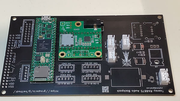
Below is the V1 4.3" RA8875 motherboard. It used sockets for the Teensy and Audio card so is fairly tall but works fine if using a deep enough box. It will work on a RA8876 also but lacks the support. On a 4.3" display the board uses the same display mounting holes.

Here is a V2 board with the Teensy 4.1 and SGTL5000 audio card soldered in for the lowest profile. Don't forget to cut the USB power trace jumper under the Teensy near the USB connector to isolate USB 5V from the board's 5V.

I later installed a LC78_05-3.0 DC-DC 3 terminal regulator replacement mounted on the motherboard and I am not seeing any noise issues so far, even on 28Mhz with a EFHW wire antenna attached and poor conditions on HF.
The 2x 10K resistors for the i2s auto correction are on the motherboard now on the back side. Here is a partially assembled V2 board. I am using only i2c encoders on this rig so I am leaving off some of the jacks. The DC DC converter installs in the existing holes on the right side along with some Tantalum caps. I do not have a battery holder yet. Be sure to use the V2 board #define or some things like encoders won’t work since the pins number are changed between board revisions.
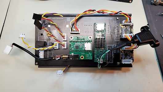
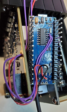
I bent the bottom side RS-HFIQ heat sink fins out at a 45 (see below) to make clearance for a RPi heat sink I stuck onto the Teensy. They line up above each other which is good, helps keep the Teensy away for the RF front end, lots of ground plane around the PA section. I have the back of the RS-HFIQ facing the Teensy thinking it might help as a RF shield. The mother board is a 4 layer board and will also help shield noise from the display.


Shown above is the minimum interconnect to get things running. 12V, Line in and Line out and the USB Host wires. I am using i2c encoders. Not shown are the wire jumpers for mic/PTT and speaker/headphone, the audio amp, and the planned internal speaker. 12V from the motherboard comes from a header on the RS-HFIQ (A6/A7 header) which has switched 14V and Gnd. I filed down the top front ridge of the DC coaxial power jack to clear the case.
Some right angle pin headers would make for even more room. I trimmed the extra long RS-HFIQ audio 2x3 header pins then bent them over a bit for more wire clearance. A few pin headers on the RS-HFIQ I swapped to the bottom side of the board (Line IN, Line Out, A6/A7 for 14V), and the BNC. I found later that I could use JST connectors with the ridges trimmed off on the audio headers, they are half the height of the standard connector.
I use a vacuum desoldering gun for the pin headers which makes flipping the header around easy. My largest desoldering tip was not large enough for the BNC legs and it took a lot of heat and some gentle prying one side at a time to work it out of the board holes. I like the ruggedness of this jack so flipped it to the bottom side (for case clearance). There is a capacitor on the bottom side feeding the center pin. Do not push the BNC all the way to the board or the BNC body will short the tiny capacitor.
With the Nano in the socket, I trimmed off the 1-2mm of exposed pin tops to prevent shorting the case.
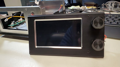
Some end views of the RF + CPU + RA8875 4.3” display stack. The case is a Hammond 1455N1601BK. Has metal end panels with plastic bezels you can opt to leave off. This is the same box as the RS-HFIQ except it is 53mm deep vs 31mm.


I used the original RS-HFIQ enclosure end plates as drill guides. With the RF board flipped from the original orientation, be sure to position the plates as needed. For the end with the audio and LEDs I put the original end plate over the jacks. Then I placed the new end plate on top and put 2 screws in the holes opposite the LEDs. This pinned the plate in place so I could put masking tape over the 2 overlapping plates. Remove the 2 screws, apply more tape and start drilling perfect placed holes. I found the PCB end plate was thick enough to center the drill bit.
For the other side I used the original plate again but it takes a bit more work to place selected holes in the plate since not only are they not in the same place, the BNC is on the opposite side of the PCB. I positioned the power switch between the 2 encoders to keep open the space between the encoder PCB and the RS-HFIQ board for a USB panel mount connector for the Teensy. The light pipes are reused.


I am reusing the RS-HFIQ Line In and Line Out jacks for Speaker and Mic/PTT since each jack has a 2x3 header with shorting blocks that when removed, isolate the jacks and allows me to run alternate signals out them. The Mic/PTT and headphone/ext speaker jack so they are not seen installed in these pictures so far.
I plan to later fit in a small 5V 1W audio amp and speaker. There is some room on the bottom under the display where a compact speaker might fit.
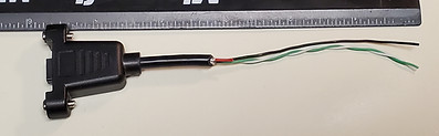
There is not enough room for a right angle micro USB connector on the Teensy so I cut micro USB panel mount extension cable off at 6" and stripped back the sheath. Cut the red 5V wire off about 1/4" from the shield/sheath end so it does not short with the shield. The 5V is not used. Put some heat shring over the sheath end and red wire.
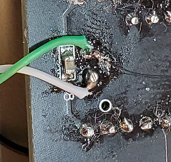
Before I soldered in the Teensy I cut the USB power jumper trace and put small solder blobs on the D+ and D- pads. You can see them here opposite the micro USB connector. I used 2 header pins inserted through the PCB holes above the D+/- pads, tinned them and soldering them so the heat on the pin melts the solder blobs. Solder the green and white wires oriented as shown. Test for continuity from the wires to the back of the USB connector pins 3 and 4.0. Run the black ground wire to a nearby GPIO connector round hole. All the holes nearest the board edge are ground, pick any one.
Keeping the USB Host cable inside the box involves putting a JST connector in the motherboard USB holes and tacking fine wires onto the Nano’s CH340G USB chip pins 5 and 6 to tap the D+ and D- USB data lines. Easier then soldering to the micro USB connector area. Purple wires seen below are on Pins 5 & 6 of the CH340G chip on the Nano. I removed the Nano micro USB connector so I do not have to drill an end panel hole for it. Like the power switch wires, I passed the wires through a mounting hole.


I have USB serial CAT control working and now running WSJT-X on my PC using the headphone audio out and the USB. A 2nd USB serial port is dedicated to CAT control via OmniRig V1 and the RS-HFIQ.ini rig file.
There is an external si5351a clock header on the RS-HFIQ. I think there is room to slip in W7GLF’s tiny 10Mhz si5351c board (designed for 22Mhz TCXO replacement for Yaesu FT-817/857/897 radios) and get an auto-switching 10Mhz external reference. The RS-HFIQ is using 25Mhz. I have made no changes to the RS_HFIQ Nano software.
Here the new Teensy Compact SDR (minus end panels) joins the family of SDRs accumulating here. Besides the K3, the other SDRs are PiHPSDR controllers built in the last half year. One is in the largest Hammond box in the 1455 series. Not seen is a new 7” Teensy SDR build in a much larger Chaval case.

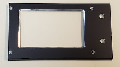
Here are some additional photos. The front panel was milled by Front Panel Express in Kent, WA. The Front Panel Designer files are on my GitHub project.

Below are the Line in and Line out audio headers. This shows how tall the various connector options are. The black are standard pin header housings, the taller while one is a standard Molex, and the shorter one is a JST (-XH variety I think)..

Below shows all the interconnect cabling ready to mate with the RS-HFIQ board.